ANZINE : CAE 기술 매거진
이전 ANZINE Home Case Study
[Global] DEM-FEM coupling for simulating the manufacturing process of all-solid-state batteries
- Koji Yamamoto
- CYBERNET SYSTEMS CO.,LTD.
- marketing@tsne.co,kr
DEM-FEM coupling for simulating the manufacturing process of all-solid-state batteries
Koji Yamamoto | CYBERNET SYSTEMS CO.,LTD.
■ Abstract
리튬이온전지(Lithium Ion Battery)의 대체로 각광받고 있는 전고체전지(Solid State Battery)는 전지양극과 음극의 사이에 전해질이 액체가 아닌 분말 형태의 불연성 고체로 대체되어 매우 안정적인 특징이 있는 차세대 배터리이다. 이러한 전고체 전지는 기존 리튬이온전지에 비해서 낮은 이온 전도도를 갖는데, 이는 전고체전지의 전해질이 분말 형태의 고체로 이루어져 있어서 자유롭게 모양을 변경할 수 없기 때문이다. 따라서 분말형태의 입자의 배열이 제품의 특성에 큰 영향을 미치는 인자이며, 고성능의 전고체전지를 개발하기 위해서는 제품을 구성하고 있는 재료의 성능을 개선하고 사용되는 분말 원료의 제조 조건을 잘 조합해야 한다.
본 고에서는 Multiscale.Sim에서 제공하는 DEM-FEM Coupling 방법을 사용하여 전고체전지의 제조공정에서 고품질, 고성능의 제품을 생산할 수 있도록 해석적으로 접근하고, 각공정에 적합한 분석 방법을 설명하겠다.
All-solid-state batteries (ASSBs) are attracting attention as safe energy storage devices for use in electric transport. However, although high safety can be guaranteed, it can be difficult to achieve high ion conductivity within ASSBs compared to conventional lithium-ion batteries (LIBs). The keys to achieving high performance lie in improving the performance of the materials that comprise the product and in optimizing the manufacturing conditions of the powdered raw materials used. This article focuses on the latter issue and introduces analysis techniques that simulate the manufacturing processes for ASSBs and even enable the performance of the final moulded products to be predicted. The article, “Filling and compression analysis of metallic powders composed of spherical particles”[1], introduced a similar analysis method using a simple model. This article is a follow-up to that report and introduces recently developed technology that enables more rigorous analysis using the discrete element method-finite element method (DEM-FEM) coupling function provided by Multiscale.Sim[2].
■ What is an all-solid-state battery (ASSB)?
Lithium-ion, nickel-metal hydride, and lead-acid batteries are commonly used in both hybrid and conventional electric vehicles. In particular, LIBs are highly practical due to their ease of charging and excellent energy density. However, one of their constituent materials, the electrolyte, is a flammable liquid that frequently combusts due to thermal runaway.
As their name suggests, ASSBs are entirely composed of solid materials, which are non-flammable, and the solid electrolyte makes ASSBs highly safe. They also have the advantage of high energy density and the potential for high capacity. On the other hand, however, technical challenges include high internal resistance due to poor connection in the contact area between the solid electrolyte and the electrode material, and low ionic conductivity of the electrolyte. Active research and development is underway to solve these problems.

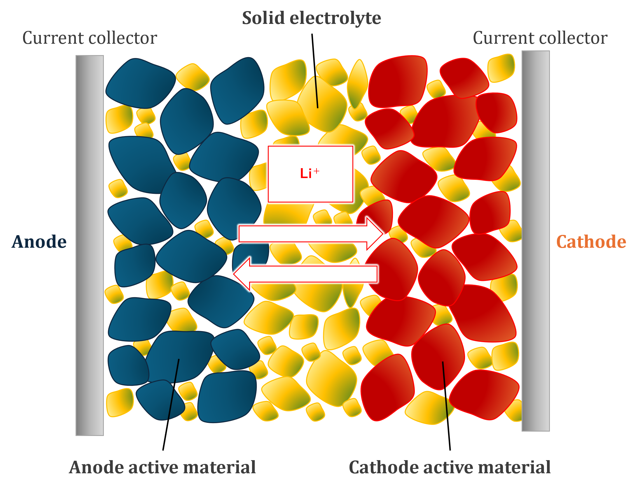
[Figure 1. Schematic internal microstructure of all-solid-state batteries]
In order to maximize the properties of the battery, its internal microstructure needs to be optimized. The following is a simplified description of a system consisting of electrolyte and active material, which are typical components. The active material, shown in blue in Fig.1, stores electrical energy, and the electrolyte (shown in red) acts as a conduit for the electrical energy.
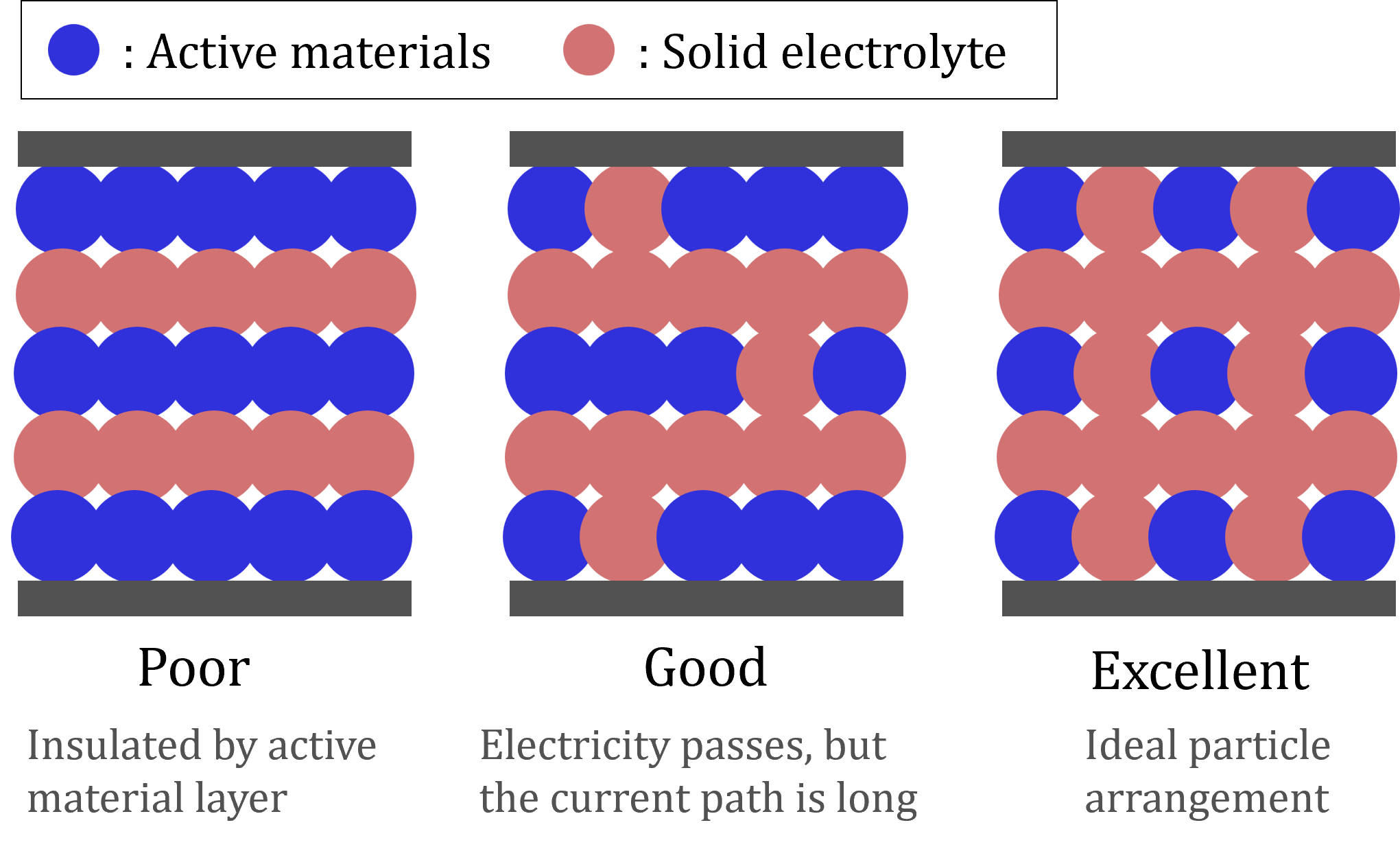
 [Figure 2. Relationship between the microstructure and performance of all-solid-state batteries]
In Fig.2a, the ionic pathway is interrupted in the middle and cannot transport any more electrical energy. The electrical path (called a percolation path) should be continuous from inlet to outlet. Ideally, for efficient ion transport a lattice-like microstructure (see Fig.2c) should be formed rather than a tortuous structure (Fig. 2b), but these microstructures are determined by the manufacturing process.
■ Manufacturing process
There are two main approaches to the production of solid-state batteries: wet and dry. Both approaches have their advantages and disadvantages, and the most suitable method is chosen based on the desired product characteristics and the production costs.
In the wet method, an organic solvent is added to the powder, which is then mixed, applied and dried. This technique is often used in sheet batteries because the liquid improves the uniformity and precision of film formation.
This article focuses on the dry process, in which powdered materials are compacted directly without the use of liquids. This reduces material wastage and simplifies the process, but has the disadvantage of making it difficult to control the microstructure.
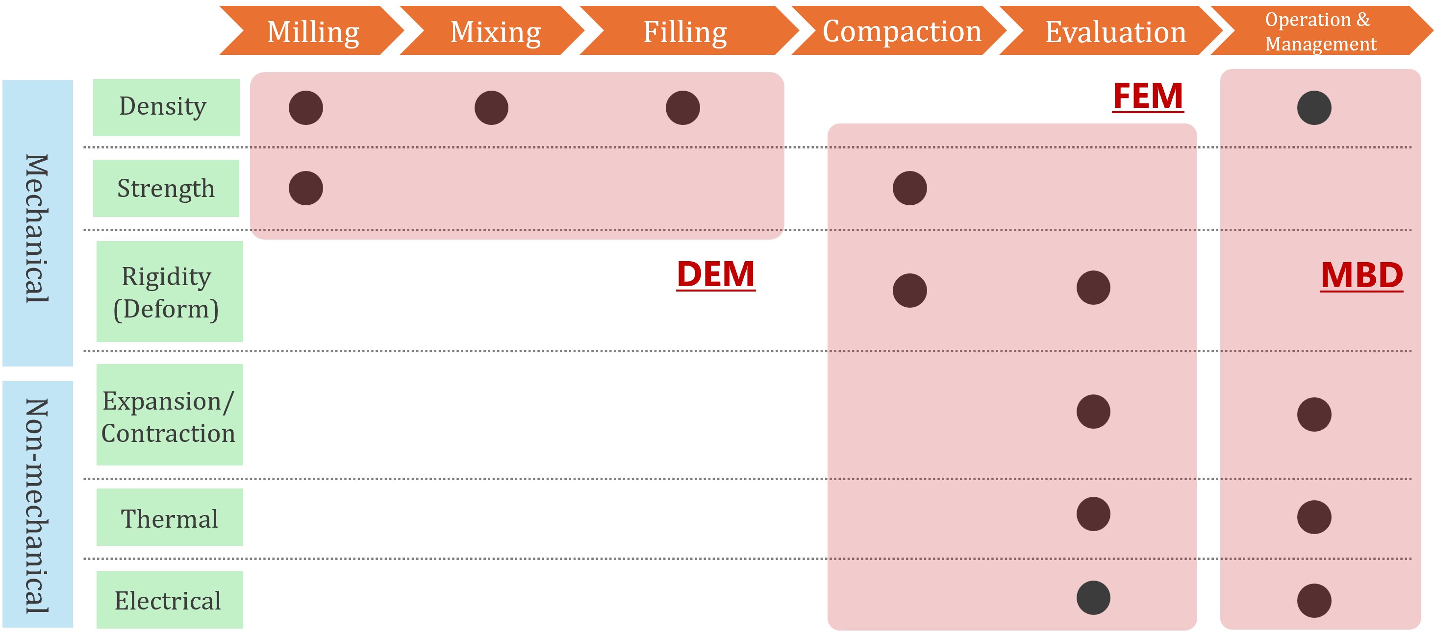
When attempting to analytically predict the performance of the product obtained using the dry method, it is necessary to consider four steps: mixing, filling, compressing, and performance evaluation, shown in Fig.3. Since the material properties change from powder to solid during the manufacturing process, appropriate analysis techniques must be used for each step. This requires knowledge of the physical properties governing the behaviour of the material in each step of the process (see Fig.3).

[Figure 3. Material constants governing each process for dry type manufacturing method of all-solid-state batteries]
Although the mixing and filling steps do not strictly result in zero particle deformation, it is the movement of each particle that governs the phenomenon. In these steps, density is the material property that determines material behaviour. During the compression process, on the other hand, particle movement is restricted and deformation is negligible, but the stiffness behaviour and strength information are important.
For problems in the first two steps where deformations are negligible, the discrete element method (DEM) is recommended for its efficiency. For compression where deformation must be considered, the finite element method (FEM) is preferred. FEM has the great advantage of accurately representing the microstructure for use in later stages of the performance evaluation process.
■ Approach to simulating each step in the manufacturing process
In the previous section we discussed suitable analysis methods to simulate each step of the dry manufacturing process. It is also important to ensure that the analysis results from the upstream processes are correctly reflected in the analysis conditions of the downstream processes otherwise the microstructure of the final moulded products cannot be accurately predicted.

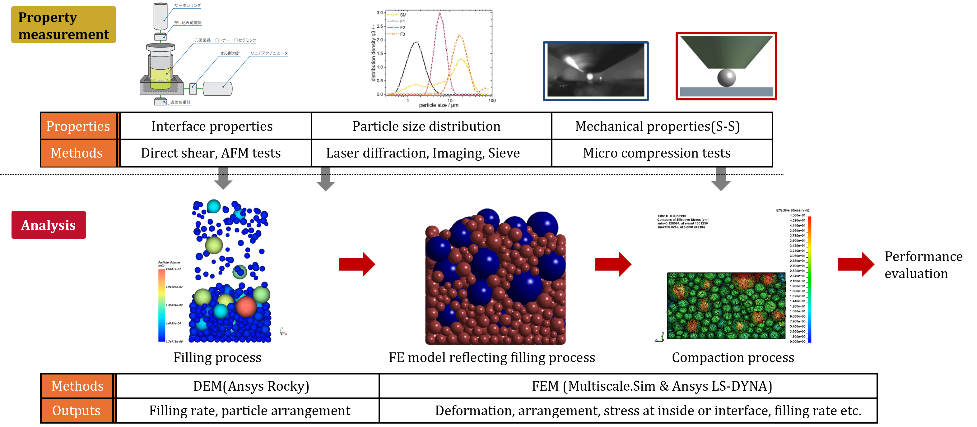
[Figure 4. Workflow to simulate a series of manufacturing process using DEM-FEM collaboration]
Fig.4 shows the analysis flow to achieve this: the DEM analysis provides information on the particle configuration. Since it is not always possible to achieve a homogeneous mixture over the entire area, the size and arrangement of each particle after filling is defined in the CAD data.
Multiscale.Sim, a multiscale analysis tool developed in Japan, provides a DEM-FEM coupling interface, and automatically converts models using primitive spherical shapes instead of STL (standard tessellation language) to create high-quality FE models. The interface also makes it easier to assign the correct material properties to each part using Ansys Mechanical, even for powders composed of multiple materials.
The resulting FE is used to perform a compression analysis. Due to the strong nonlinearity involved, we recommend using the explicit method in Ansys LS-DYNA. Fig.4 summarizes the particle material information required to analyse each step of the process and the methods used to obtain this information.
Ansys Rocky offers various functions to calibrate material properties from these test results. The properties required for DEM analysis can be easily identified by comparing experimental data and analytical results. Micro-compression tests generate the mechanical properties of the particles necessary for the compression analysis. The FE analysis also reproduces the load-displacement characteristics of compressing a single particle obtained by inserting the material properties as unknown parameters. The actual material properties are identified retrospectively by combining the experimental and analytical results.
The microstructure obtained from the compression analysis is used to evaluate the performance of the final product, which requires the use of Multiscale.Sim’s homogenization method. As mentioned in Fig.2, battery performance is determined by various geometric factors, including the percolation path of the solid electrolyte. Electrical tests conducted on virtual materials using the homogenization method enable the macroscale properties such as internal resistance to be predicted. For details on the homogenization method, please refer to the article “Predicting the strength of composite materials using Ansys Software”[3].
■ Use cases
The following is a brief description of the use case to analyse the production process from filling to compression. In the filling step, active material and solid electrolyte blended in a given weight ratio are placed in a cubic mould with an open top.
The solid electrolyte, which has a particle size in the order of submicrons, is strongly affected by microscopic adhesion. The adhesion force and coefficient of friction between each material, and between the mould and the material are measured using the single plane shear test and reflected in the analysis. The mass flow rate is carefully determined as a condition of particle delivery.

[Figure 5. Analysis results for filling process which is depended on the mass flow rate of the particle]
Since this value is difficult to measure, it is used as a tuning parameter to ensure that the bulk density after the filling process matches the experimental results to ensure consistency with the actual problem. Fig.5 plots the relationship between mass flow rate and bulk density after filling.
Due to computational costs, it is not practical to use the same conditions as in the experiments, so the mould size is made smaller than in reality. (The use of a coarse-grained method is also not recommended in order to maintain consistency with the compression process). The analysis results showed a strong dependence on the mass flow rate. If clear conditions cannot be determined in the actual process, the conditions should be adjusted by comparing the experimental result with the analysis results.

[Figure 6. Stress-strain curves at 12 typical locations obtained by compression analysis. The analysis results could be validated in the small strain region. Specific value for each axis is hidden due to confidentially reasons]
Fig.6. summarizes the results of an example analysis of the compression process. These results show the macroscopic stress-strain relationship obtained from the FE model focusing on the 12 representative regions shown in the figure. Particles can be crushed in high pressure regions, but that was not considered in this case. For the particles, the elasto-plastic properties identified in the micro-compression tests for all materials were taken into account.
Particles partially out of the extraction area were cut and modelled to fit within the rectangular bounding box. Since the solid electrolyte has a lower stiffness than the active material, the solid electrolyte is preferentially deformed as it is compacted, which may cause partial breakdown of the percolation path. It is therefore important to check the appropriate material mix ratio and the particle arrangement prior to compacting based on the results of the analysis that considers the deformed state of the particles.
The graph shows that the results are somewhat dependent on the area being sampled. This may be due to different mixing conditions at different locations or an insufficient sample size. In any case, the experimental results obtained are close to the average value of these analysis results, showing that the actual problem can be reproduced with a certain degree of accuracy, at least in the small strain range.
Conclusion
This article introduced an analytical technique to predict the performance of all-solid-state batteries.
Performance predictions can be made using Multiscale.Sim, but it requires a microstructural model. We therefore introduced a method to analyse a series of manufacturing processes to obtain a microstructure model incorporating the effects of each step in the process.
Since the raw materials for solid-state batteries change from powder to solid during manufacturing, the appropriate analysis method varies according to the characteristics of each process. Multiscale.Sim’s DEM-FEM interface allows you to perform analyses of downstream manufacturing processes using models that accurately reflect upstream processes.
■ References
[1] K. Yamamoto, “Filling and compression analysis of metallic powders composed of spherical particles”, EnginSoft Newsletter, Autumn 2020.
[2] www.cybernet.co.jp/ansys/product/multiscale/en/
[3] K. Yamamoto, “Predicting the strength of composite materials using Ansys Software”, EnginSoft Newsletter, Summer 2020.
Credit: First published in the Futurities - Autumn 2024 edition by EnginSoft SpA.
■ About CYBERNET
CYBERNET is a leading CAE company established in 1985, headquartered in Tokyo, Japan. Their corporate vision is "Creating a sustainable society and inspiring the world through technology and ideas”. Their goal is to solve the problems of their customers, who face increasingly diverse and complex technological issues every day, with technology and ideas that exceed their expectations, and to lead them to the next level of innovation. CYBERNET is an Apex Channel Partner and a Technology Partner (Software) of Ansys. They have been developing Multiscale.Sim since 2007 and it’s being used by many customers in Japan and in other countries.
For more information :
- visit: www.cybernet.co.jp/ansys/product/lineup/multiscale/en/
- email: cmas@cybernet.co.jp


 ㈜태성에스엔이


